Flow control
Feed, product, recycle, cooling water, fuel, air and dosing streams; selection considers installed characteristic, rangeability and minimum controllable flow.
 Petro Pendar Pars
Project-based sourcing of industrial control valves, actuators, positioners and accessories—aligned with process data, control philosophy, project specifications, inspection requirements and delivery scope.
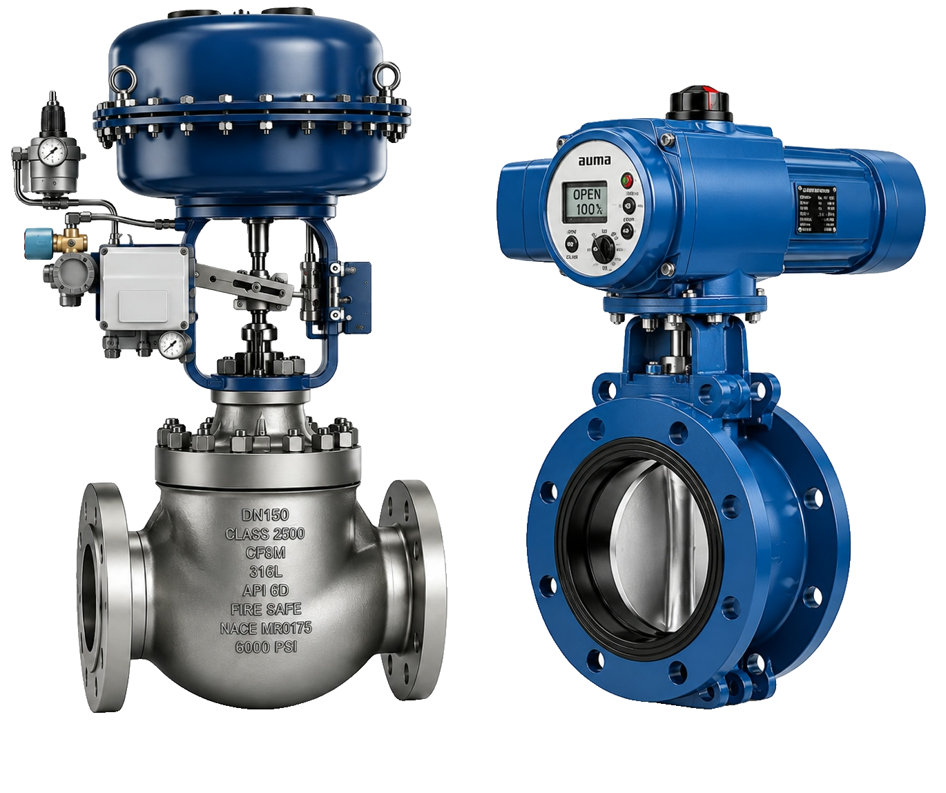
A control valve is the final control element that changes flow area in response to a control-system command.
Stable regulation of flow, pressure, temperature or level depends on more than nominal pipe size. The body and trim manage the fluid and pressure drop; the actuator supplies force or torque; the positioner closes the local position loop; and accessories implement air conditioning, trip logic, speed and feedback.
Minimum, normal, maximum, start-up and upset cases can produce different Cv, opening, outlet velocity, noise and cavitation margins. Selection should therefore be based on the operating envelope and installed behavior, not a catalogue size alone.
Petro Pendar Pars is an industrial sourcing and procurement company. PPARS coordinates inquiry definition, vendor evaluation, technical and commercial clarification, documentation, inspection and logistics. This page does not imply manufacturing, exclusive representation, official distributorship or ready stock.
The control objective determines capacity, response, flow characteristic, shutoff and safe failure behavior.
Feed, product, recycle, cooling water, fuel, air and dosing streams; selection considers installed characteristic, rangeability and minimum controllable flow.
Upstream, downstream and differential-pressure duties, including gas reduction and letdown service where noise and outlet velocity may govern.
Heating or cooling media to exchangers and reactors; valve response must be considered with process lag, loop tuning and safe fail action.
Vessels, separators, columns and tanks; available pressure drop, flashing and low-flow stability are often decisive.
Steam, condensate and feedwater duties can combine high differential pressure, temperature cycling, cavitation and erosion risk.
Fast recycle service requiring adequate installed capacity, low dead time, defined stroke time and coordinated actuator-accessory dynamics.
Oil & gas, refineries, petrochemical plants, power plants, chemical, steel, mining, water and wastewater projects impose different material, test and documentation requirements.
Body style is selected from controllability, capacity, pressure drop, fluid condition, shutoff, footprint and maintenance constraints.
Stable linear throttling with broad trim options for accurate modulation, low flow, high pressure drop, noise or cavitation control.
Typical use: Pressure/temperature control, steam, feedwater and demanding process loops.
Quarter-turn family combining compact installation and high capacity; seat and trim geometry determine throttling behavior.
Typical use: High-capacity process and utility flow control.
Low-loss, high-capacity option for larger lines; disc, shaft, seat and opening limits govern torque and stability.
Typical use: Cooling water, air, gas and large utility lines.
Full or characterized/segmented ball designs provide high capacity and useful rangeability.
Typical use: Dirty fluids, high-capacity modulation and applications needing strong shutoff.
Engineered flow paths, staged trims or hardened materials manage cavitation, flashing, noise, vibration and erosion.
Typical use: High-energy letdown and critical refinery, petrochemical or power duties.
High-capacity, fast-response package for compressor recycle; dynamic performance is reviewed with sizing.
Typical use: Centrifugal compressor protection.
Mixes or diverts compatible streams; port arrangement and combined-flow balance must match piping duty.
Typical use: Heat-transfer and bypass circuits.
Turns flow through 90° and can suit high-pressure letdown or flashing when outlet design is appropriate.
Typical use: Drain, letdown and erosive services.
Integrated valve, actuator, positioner and accessories configured and tested for proportional control.
Typical use: Skids, packages and plant control loops.
Linear valves normally use diaphragm or piston linear actuation; rotary valves use quarter-turn solutions such as rack & pinion or scotch yoke.
Linear spring-and-diaphragm actuation commonly paired with globe valves; simple fail-safe action and good modulating behavior.
Linear single- or double-acting cylinders for higher thrust, longer travel or faster stroking.
Compact rotary actuator mechanism for quarter-turn valves—not a typical globe-valve linear actuator.
Rotary mechanism with a non-linear torque profile that can provide higher end-of-travel torque.
Useful where instrument air is unavailable; verify modulating duty, speed, torque/thrust, enclosure and fail strategy.
High-force solution for demanding or remote service; power unit, stored-energy fail action and maintenance are package considerations.
The positioner compares the command with actual travel and drives the actuator until the requested valve position is reached.
Auto-calibration, travel feedback, diagnostics and device status; required diagnostic depth and asset-management integration must be specified.
Converts an electrical command—commonly 4–20 mA—into pneumatic actuator control.
Uses a pneumatic command signal for legacy architecture or installed-base replacement.
Digital configuration and diagnostics superimposed on the 4–20 mA loop, subject to host compatibility.
Fully digital interface requiring compatible host, segment design, device revision and function-block philosophy.
Digital process interface selected to match the control-system architecture and project device profile.
Accessories must be selected as one pneumatic and electrical circuit, especially for fast or safety-related action.
Specify flow capacity, pressure rating, materials, ambient range, ingress protection, hazardous-area approval, failure mode and electrical connection for every accessory. Tubing volume and restriction also affect response.
Comparable proposals begin with consistent process cases, mechanical requirements and control-system interfaces.
Fluid composition and phase; density, viscosity, vapor pressure and solids; minimum, normal, maximum and upset flow; inlet/outlet operating pressure; design pressure; operating/design temperature.
Calculate Cv for every case using the applicable liquid, gas or steam method. Select valve size for controllable travel and margin—not by copying line size.
Pressure class, end connection, face-to-face, body/bonnet material, piping class and pressure-temperature limits.
Trim and seat materials, seat leakage class, packing and required equal-percentage, linear or other flow characteristic.
Quantify aerodynamic noise, liquid cavitation, flashing, outlet velocity, vibration and any need for staged trim or downstream devices.
Separate corrosion compatibility from erosion caused by velocity, droplets, solids and impingement; hard trim is not a universal remedy.
Define Fail Open, Fail Close or Fail In Place from the process safety requirement and state the initiating utility/signal failure.
Verify thrust or torque through travel, shutoff differential pressure, packing/seat loads, available utility, safety factor, stroke time and cycle rate.
Signal, protocol, diagnostics, feedback, hazardous-area zone/division, gas/dust group, temperature class, protection method and ambient range.
Send the available datasheet or process cases. PPARS can identify missing RFQ inputs and coordinate sourcing clarification without replacing the purchaser’s engineering approval.
Control valves may be specified or supplied in accordance with applicable project and manufacturer standards; listing a standard is not a PPARS certification claim.
The RFQ should state the exact edition, applicable part, acceptance criteria and evidence required. API 6D applies only within its pipeline-valve scope. Functional-safety, fire-safe and fugitive-emission claims must be supported by the proposed manufacturer’s documentation.
No unverified brand, authorization or stock relationship is published. Availability is confirmed for each RFQ against the nominated manufacturer, AVL, origin, model and delivery conditions.
Share the approved manufacturer list, model family and permitted manufacturing locations.
Provide nameplate, serial/model code, dimensions and control interfaces; alternatives are compared only where the project permits them.
PPARS keeps the technical, commercial, documentation and delivery requirement connected through the sourcing process.
Check completeness, consolidate clarifications and maintain revision alignment.
Route the inquiry around the defined package, approved sources, origin constraints and delivery terms.
Review supplier identity, proposed manufacturing route, response completeness and required qualification evidence.
Normalize compliance, deviations, sizing basis, materials, actuation, accessories, tests and documents for purchaser review.
Compare scope, exclusions, validity, payment, Incoterms, delivery, warranty and documentation conditions.
Coordinate agreed notifications, hold/witness points and records when an ITP is part of the order.
Track drawings, datasheets, certificates, reports, manuals and final dossier requirements.
Coordinate packing and delivery information, and source commissioning or maintenance spares from tag/model/BOM data.
Answers to common selection and RFQ questions.
A control valve is the final control element that varies flow area in response to a controller signal to regulate flow, pressure, temperature or level. A complete package combines the valve body and trim, actuator, positioner and required accessories.
Provide fluid properties and phase, minimum/normal/maximum flow, inlet and outlet pressure, temperature, line and valve size, pressure class, materials, leakage, characteristic, fail action, hazardous area and project standards.
Cv is a flow coefficient. In US customary terms it is the flow of 60°F water in US gpm that produces a 1 psi pressure drop. Required Cv must be calculated for each process case.
The terms normally describe actuator technology. Pneumatic actuation often offers fast response and simple spring-return fail action; electric actuation can suit sites without instrument air. Compare duty cycle, speed, fail behavior, utilities and hazardous-area requirements.
Match required thrust or torque through travel, maximum shutoff differential pressure, stroke time, cycling, available utility, safety factor and required Fail Open, Fail Close or Fail In Place behavior.
It compares the command with measured valve travel and regulates actuator input until the requested position is reached, helping overcome friction and process forces.
They define the intended valve position after a specified loss of signal or utility. The process safety study determines which position reduces risk; the initiating failure and stored-energy method must be stated.
Cavitation occurs when liquid pressure falls below vapor pressure and then recovers, collapsing vapor bubbles and potentially causing noise, vibration and damage.
Send the datasheet, tag list, process cases, actuator and positioner requirements, area classification, standards, documentation and inspection requirements, quantity and delivery location.
PPARS can evaluate sourcing requirements for oil, gas, refinery, petrochemical and power projects subject to the approved datasheet, vendor constraints, documentation, inspection and commercial conditions.
Mark values as minimum, normal, maximum, design, required or vendor-proposed so assumptions remain visible.
Links below point only to existing PPARS product sections.
Include confirmed values and identify open items. PPARS will review RFQ completeness and coordinate sourcing, quotation, documentation, inspection and delivery requirements.